Posts

Alien attack alarm 2

Image
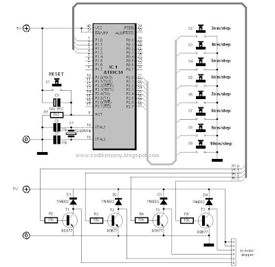
By Sony Sodikin www.sodikinsony.blogspot.com This simple project is same with alien attack alarm 1 project before, but in this project a long-varied tones output is produced longer than project before. Circuit Diagram Program Listing /*********************************************************** Title : Alien attack alarm 2 Author : Sony Sodikin : http://www.sodikinsony.blogspot.com Date : February,2009 Processor : AT89C51 ***********************************************************/ #include #define SPEAKER P1_7 #define ON 0 #define OFF 1 void delay(int z) { unsigned int x; for(x=0;x } main() { int z; for(;;) { for(z=1;z<=1000;z++) { SPEAKER=ON; delay(z); SPEAKER=OFF; delay(z); } for(z=1000;z>=1;z--) { SPEAKER=ON; delay(z); SPEAKER=OFF;

Alien attack alarm 1

Image
By Sony Sodikin www.sodikinsony.blogspot.com Have we, the human race back-engineered alien technology as a ways of ensuring that we would, at least, have a fighting chance if we were invaded by alien beings? Although we don’t have anti gravity technology, superior technology, and so on, don’t worry, I have made an Alien attack alarm to warn to you about it. This simple project is same with projects before. Circuit Diagram Program Listing /*********************************************************** Title : Alien attack alarm Author : Sony Sodikin : http://www.sodikinsony.blogspot.com Date : February,2009 Processor : AT89C51 ***********************************************************/ #include #define SPEAKER P1_7 #define ON 0 #define OFF 1 void delay(int z) { unsigned int x; for(x=0;x } main() { int z; for(;;) { for(z=1;z<=1000;z++) { SPEAKER=ON; del

Multi-Tones Simple Speaker Interface 2

Image
By Sony Sodikin www.sodikinsony.blogspot.com *****““Our main business is not to see what lies dimly at a distance, but to do what lies clearly at hand”****** This project shows how we can interface AT89C51 to a small speaker. In this project a continuous multi tones output are produced on the speaker. The speaker normally operates when an alternating signal is applied with the frequency in the audible range. The speaker is connected to bit 7 of port 1 via a PNP transistor and the speaker is ON when the output of the port is at logic HIGH. The program is written in SDCC. Circuit Diagram Program Listing /*********************************************************** Title : Multi-Tone Simple Speaker Interface Author : Sony Sodikin : http://www.sodikinsony.blogspot.com Date : February,2009 Processor : AT89C51 ***********************************************************/ #include #define SPEAKER P1_7 #define ON 0 #define

Simple Speaker Interface 2

Image
By Sony Sodikin www.sodikinsony.blogspot.com *****““Our main business is not to see what lies dimly at a distance, but to do what lies clearly at hand”****** This project shows how we can interface AT89C51 to a small speaker. When a push-button switch is pressed, the speaker will turn on and off 3000 times (about 19 second) and then stop. The speaker normally operates when an alternating signal is applied with the frequency in the audible range. The speaker is connected to bit 7 of port 1 via a PNP transistor and the speaker is ON when the output of the port is at logic HIGH. The push-button switch is connected to bit 0 of port 3. The program is written in SDCC. Circuit Diagram Program Listing /*********************************************************** Title : Simple Speaker Interface 2 Author : Sony Sodikin : http://www.sodikinsony.blogspot.com Date : February,2009 Processor : AT89C51 ***************************

Simple Speaker Interface 1

Image
By Sony Sodikin www.sodikinsony.blogspot.com *****““Our main business is not to see what lies dimly at a distance, but to do what lies clearly at hand”****** This project shows how we can interface AT89C51 to a small speaker. In this project a continuous single tone output is produced on the speaker. The speaker normally operates when an alternating signal is applied with the frequency in the audible range. The speaker is connected to bit 7 of port 1 via a PNP transistor and the speaker is ON when the output of the port is at logic HIGH. The program is written in SDCC. Circuit Diagram Program Listing /*********************************************************** Title : Simple Speaker Interface 1 Author : Sony Sodikin : http://www.sodikinsony.blogspot.com Date : February,2009 Processor : AT89C51 ***************

3-10ms/step Stepper Motor Controller

Image
By Sony Sodikin www.sodikinsony.blogspot.com This is a simple stepper motor controller project. A stepper motor is connected to bit 0, 1, 2, and 3 of port 1 via four BD677 transistors. Eight push-button switches are connected to port 2 to select the required time per step (3 mili second per step – 10 mili second per step). Timer 0 is used to generate time delays. The program is written in MCS-51 family macro assembler. Circuit Diagram Program Listing ;*********************************************************** ; Title : 3-10ms/step Stepper Motor Controller ; Author : Sony Sodikin ; : http://www.sodikinsony.blogspot.com ; Date : April,2004 ; Processor : AT89C51 ;*********************************************************** org 0h mov tmod,#01H start: jnb P2.0,step_3ms

Red Cyclon Eye

Image
By Sony Sodikin http://www.sodikinsony.blogspot.com/ This project turns on the LEDs connected to port 0 of the microcontroller in sequence, making like a Cylon with the light bouncing back and forth. The data is displayed with about 1/2 second delay between each output pattern. If you don’t know what a Cylon is, try Googling Battlestar Galactica. Circuit Diagram Program Listing /*********************************************************** Title : red cyclon eye Author : Sony Sodikin : http://www.sodikinsony.blogspot.com Date : September,09,2008 Processor : AT89C51 ***********************************************************/ #include void delay(void) { int i; for(i=-32768 ; i<32767 ; i++); } void main(void) { while(1) { int j; for(j = 1; j <= 128;